

No images found.
A brushless motor has one wear part, and it is the bearing. Everything else that stops a BLDC system from working sits in the controller, in the wiring, or in the way the machine was specified. That matters for troubleshooting, because a fault that presents as a motor problem very often is not one, and a technician who starts by replacing the motor has a good chance of replacing a working part. The useful question is not what failed inside the motor, but which of the three things outside it caused the motor to be blamed.
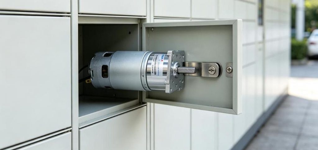
The Motor Is the Part Least Likely to Be at Fault
Strip a small BLDC down and there is very little to go wrong. The rotor carries magnets and no windings, so there is no commutator to wear, no brush to wear down, and no centrifugal force acting on soldered joints. The stator windings are stationary, which is why a BLDC cools better than a brushed motor of the same frame and why its windings last longer.
What remains is bearings, insulation, magnets and balance. Of those, bearings account for most motor-side failures, and they usually fail because of the load the machine put on them rather than because of the motor: an overhung load carried too far from the flange, or a belt tensioned harder than the shaft was rated for.
When the Motor Does Fail, It Is Usually Thermal
The two genuine motor failures that are not bearing related are both heat. Winding insulation degrades when the winding runs above its class temperature for long enough, and the magnets lose strength when the rotor gets hot.
The magnet case is worth understanding because it does not announce itself. A rotor that has been overheated produces less back EMF at the same speed, so the controller drives it harder to hold speed, which produces more current, which produces more heat. Performance falls gradually and the machine is described as tired rather than broken. Where the rotor uses neodymium magnets, which is usual when the frame is small and the torque density is high, heat is the mechanism; ferrite rotors behave the other way and are more at risk from cold. Either way, a demagnetized rotor does not recover, and the useful outcome of diagnosing it is finding the duty or stall condition that caused it.
The Failures That Are Actually in the Drive
Most dead BLDC systems die here, and the three common components fail in recognizably different ways.
A failed MOSFET usually fails short. The result is a brake rather than a motor: the shaft becomes hard to turn by hand, and the controller trips on overcurrent the moment it is enabled. A MOSFET that fails open gives the opposite symptom: no torque at all on one phase, and a pronounced shudder as the motor tries to start.
A dried electrolytic capacitor on the DC bus does not stop the motor; it makes the motor unreliable under load. Capacitance falls, ripple rises, and the controller trips or resets when the load increases, which reads as a motor that cannot take load. Capacitor life roughly halves for every ten degrees of sustained temperature rise, so a controller mounted next to a warm gearbox ages faster than its rating suggests.
The third is the gate driver, and it fails in a way worth knowing about. A driver that no longer switches cleanly can destroy the MOSFET it drives, so the visible fault is a dead transistor and the actual fault is one layer behind it. A replacement device that fails again within minutes is the signature. In that case the next component to change is the driver, not another MOSFET.
The Symptom That Looks Like a Weak Motor
Sensorless drives infer rotor position from back EMF, and at zero speed there is none. The controller is guessing during startup, and the guess is poor. A motor that stutters, jumps backwards, or refuses to start against a load is behaving exactly as a sensorless drive does when the load is too stiff for it, and no amount of motor replacement will fix that.
The same mechanism explains a motor that runs badly at very low speed and perfectly at speed. It is a control limitation, not a motor fault, and the answer is a Hall-sensored version or a different starting profile. This is worth checking before the motor is removed, because it is the most common misdiagnosis in this product class.
A Test Sequence That Separates Them
Four measurements, in this order, will place the fault in the motor, the harness, or the drive.
Measure resistance across each pair of phase leads with the drive disconnected. The three readings should match closely; one that is markedly different indicates a winding fault, and an open circuit on one pair indicates a broken lead or a failed joint.
Spin the shaft by hand or with a drill and measure the voltage between phase pairs. A healthy motor produces three similar AC waveforms as it turns, roughly equal in amplitude. A weak or uneven set points to a magnet or winding problem. The test takes about a minute.
With the drive powered, turn the shaft slowly by hand and watch the Hall signals if the motor has them. Each sensor should toggle cleanly as the rotor passes. A sensor that sticks, or that toggles in the wrong order, will make the controller commutate at the wrong time and produce exactly the shudder a bad MOSFET produces.
Then swap the drive, not the motor, and see whether the fault follows. This is the fastest test in the list and the one most often skipped.
Why a BLDC Cannot Be Judged Without Its Drive
A brushed motor can be checked on a bench with a battery and a tachometer, and the reading means something. A BLDC cannot. Its speed, torque, starting behavior and efficiency are properties of the motor and the controller together, and the same motor can be excellent behind one drive and unusable behind another.
That is why a returned BLDC is so often a mismatch rather than a failure. A 38 mm unit such as the BLDC-38S behaves differently on a drive set for a different pole count or a different commutation mode, and the machine builder sees a motor that will not run. Before a failure report becomes a warranty claim, it is worth confirming that the drive settings match the motor, that the phase order is correct, and that the supply holds up under starting current.
What to Send With a Failure Report
Five items turn a report into a diagnosis: the supply voltage measured at the controller under load, the drive model and its settings, the duty expressed as running and rest time, the temperature at the motor when the fault appears, and whether the symptom occurs at startup, at speed, or only under load. With those, the four measurements above usually locate the fault in one exchange rather than three.
Common BLDC Motor Failure Modes and Troubleshooting Guide
A brushless motor has one wear part, and it is the bear […]


