

No images found.
A datasheet lists 2000 N. The same actuator ordered with a longer stroke will not push 2000 N, and nothing about it is defective. One dimension changed, and with it the mechanism that decides the figure. In compression the extending rod is not a piston but a column, and a column gives way by buckling long before its material reaches yield. Load ratings tend to be compared as though they were a property of the actuator, like supply voltage. They are a property of the actuator in a particular geometry, and the geometry is usually settled later, by someone else, from a drawing.
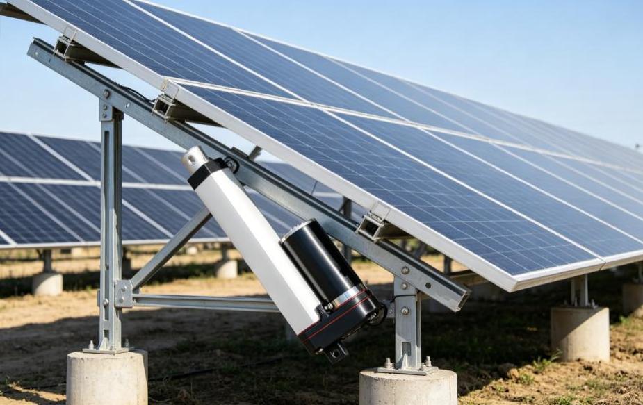
In Compression the Rod Is a Column, Not a Piston
If the 2000 N quoted for ZGB800 at 12 V describes the push direction and is measured at a 200 mm stroke, the same model at 400 mm is limited by buckling to about 500 N before any other derating. A customer who needs 1200 N over 400 mm has not bought a slightly weaker actuator. He has bought one that will bow the first time the mechanism meets an obstruction.
Once the reference stroke is known the correction is arithmetic: published figure, times reference stroke over actual stroke, squared. The difficulty is that many catalogues omit the reference stroke, which leaves the number unusable outside the length it was measured at. Asking for it is a more productive question than asking for the peak load.
Pulling is a different case. In tension the rod is not a column, so the limit that governs push has no equivalent on pull, and a single figure quoted without direction hides which one it describes.
The Mounting Changes the Answer by a Factor of Four
Because K is squared, the end conditions are not a detail. Two clevis ends, the usual arrangement on this class of actuator, give the pinned-pinned case with K of 1.0. Fixing one end and leaving the other free gives 2.0, which cuts capacity to a quarter. Fixing both gives 0.5, which raises it fourfold.
Nothing on the actuator changes when it is bolted down differently. What changes is whether the published figure still applies. A rear mount clamped rigidly to a frame while the rod end floats in an unslotted hole is neither of the clean cases, and it is what appears when a bracket is designed after the actuator is chosen. Trunnion mounting shortens the unsupported length instead of altering K, and is the usual answer when a long stroke has to push hard.
Side Load Shows Up Before Lost Thrust Does
An actuator develops force along its axis and nowhere else. When the load’s line of action sits at an angle to that axis, the useful component is the axial force times the cosine of the angle, so the axial force must exceed the load by the reciprocal of that cosine. The remainder arrives as side load.
The two penalties do not grow together. At 10 degrees the actuator produces about 1.5 percent more thrust than the load needs, while nearly 18 percent of the load is fed in sideways. At 30 degrees the thrust penalty is around 15 percent and the side load is 58 percent of the load. A misalignment that looks negligible in the force calculation is often the whole reason a seal fails.
What side load does inside the actuator is worse than what it does to the force budget. It puts a bending moment on the rod and the screw, presses the rod against its bushings and deforms the seal against the bore, and once that seal is deformed the ingress protection on the label no longer describes the assembly. The remedy is not a larger actuator but an external guide: rails, guide rods or linear bearings that carry the perpendicular component and leave the actuator with pure axial force. In a hinged application the guide is a requirement, not a refinement.
The Number on the Drawing Is Not the Space You Need
Stroke describes travel, not the length of the closed actuator. On ZGB758 and ZGB800 the minimum mounting distance is stated as S plus 100 mm, so a 400 mm stroke occupies 500 mm between pins when fully retracted. Machines tend to be laid out around the stroke, with the retracted envelope checked late, and that is where a selection that looked right becomes a bracket redesign.
Long strokes also lower the speed the assembly can run at, because the critical speed of a slender screw falls with the square of its length in the same way the buckling load does. Where an application needs both long travel and fast movement, that constraint belongs in the enquiry rather than in commissioning.
The Screw Decides What Happens When the Power Is Cut
A trapezoidal or ACME screw drives a nut in sliding contact. Efficiency typically falls between 30 and 50 percent depending on lead angle, and the loss leaves as heat in the nut. The same friction makes the screw self-locking: a single-start screw with a small lead angle holds position with the power removed. A ball screw runs above 90 percent and lasts far longer under continuous cycling, but it back-drives under a gravity load and needs a brake to hold. Coarse multi-start ACME screws can back-drive as well, so self-locking should be confirmed for the specific screw rather than inferred from its type.
Efficiency has a second consequence that is easy to miss. Where the duty is quoted as S2 with a stated time, as on these models, the limit being protected is thermal, and the heat reaching the nut is input power minus output power. At 35 percent efficiency an output of 7 W means about 20 W going in, with 13 W deposited inside the housing. That is why a short-time duty exists, and why a low-efficiency screw with a generous load rating may not survive a cycle rate that a ball screw handles without complaint.
What to Send With the Enquiry
Four numbers decide whether a catalogue rating applies: push force and pull force at the worst point of the stroke, stated separately; the stroke, together with the space available when fully retracted; how both ends will be mounted, and whether the load is carried by external guides or by the actuator alone; and the duty, expressed as movement time and rest time in a repeating cycle rather than as a percentage. The temperature range, and whether water is present while the rod is extending, complete the picture. With those, a stroke can be proposed that holds the required force instead of one that merely matches the drawing.
Why a Linear Actuator’s Load Rating Depends on Its Stroke
A datasheet lists 2000 N. The same actuator ordered wit […]


